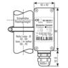
Description
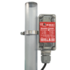
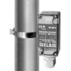
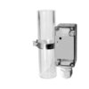
Magnetically actuated changeover switch, which permanently changes its electrical switching state as a result of a magnetic system passing by, depending on the direction of movement.
Technical Data
Properties
- Protection class EN60529
- IP 65
- Operating temperature
- –25...+70 °C
- Wire cross-section max.
- 1,5mm²
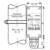
- Switching point distance between two contacts
- min. 40 mm
- Switching hysteresis
- ca. 10-15 mm
Material
- Housing
- Polycarbonat
- Mounting clip
- V2A, Kabelbinder (PP)
- Rivet
- V2A
- Screw connection
- M 20 x 1.5, Polyamid
Weight
- BK-390-50
- 137 g
- BK-390-63 / BK-380
- 140 g
Switching contact
- Switching voltage
- 5...250 V AC/DC
- Switching current
- 1mA...6 A AC/DC
- Switching capacity(min.)
- 300 VA, 60 W
- Switching capacity(max.)
- 5 mW
BK-390 application-specific configuration
BK-390 - [ 1 ] - [ 2 ] - [ 3 ]
product description
Der bistabile Kontakt BK-390 kann auch mit Kabelbindern befestigt werden. Diese sind für Rohre mit einem Durchmesser von 25-70 mm geeignet.
Further product information
The switching status of the BK-380, BK-390 is displayed in the status window of the housing cover. When the housing is open, the bistable changeover contact can be operated manually. This simplifies commissioning and enables tests of the downstream control equipment.
A stainless steel pipe clamp is used for mounting on bypass or sightglass pipes with diameters of 32-50 mm or 50-70 mm. The bistable contact BK-390 can also be fixed with cable ties. These are suitable for pipes with a diameter of 25-70 mm.
The switching unit of the BK-380, BK-390 consists essentially of a microswitch, the permanent magnet actuator and the ferromagnetic holding element.
When a magnetic system passes the active surface of the BK-380, BK-390, the holding force between the actuator and the holding element is released and a rotary movement of the actuator is triggered, which causes the microswitch to switch. The almost rotationally symmetrical shape of the actuator and the magnetic stabilisation of the switch positions ensure maximum resistance to shock and vibration.
shock and vibration resistance is achieved.
